CASE 26: Revision of a loose cup due to massive osteolysis from polyethylene wear, using a custom 3D-printed cup and extreme leg length correction

The Story
“Rose is a 57-year old female who presented with an interesting but complicated orthopaedic history. As a young child, she had been diagnosed with developmental dysplasia of the hip. Throughout her early years, she had received multiple operations in an attempt to maintain an acetabulum on the right side.
At the time of presentation, she had received two previous hip replacements. These had led to a massive right sided pelvic defect, with superior migration of the acetabular cup and complete loss of the medial acetabular wall.
The defect was too large to correct with an off the shelf component. The only way forward was to use a custom implant to fill the defect and correct the position of her right hip joint.”
The Evidence

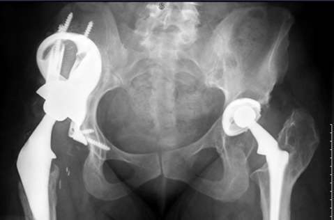
Anteroposterior (AP) radiograph showed massive acetabular bone loss with superior migration of the right acetabular cup. This left the patient with a severe leg length discrepancy which is not quantifiable from this radiograph.

The red lines highlight the leg length discrepancy in this patient while she is standing. This can be measured using software.

Pre-op EOS - an EOS image of the patient sitting (in a functional position). This again highlights the superior migration of the implant.
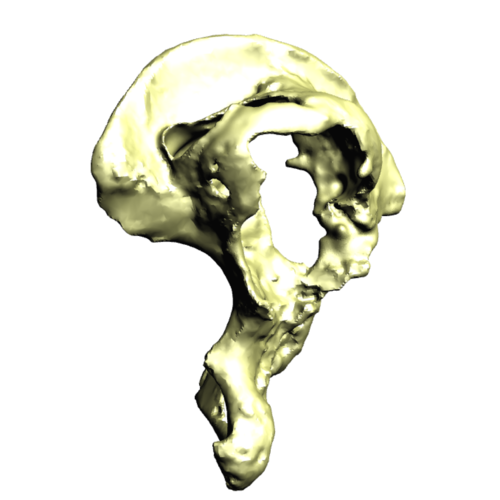
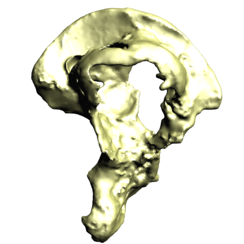
This is a 3D reconstruction (from a CT scan) of this patient’s right hemipelvis.
It highlights the extent of her acetabular defect. The medial wall is completely missing - however, the anterior and posterior columns are still intact.
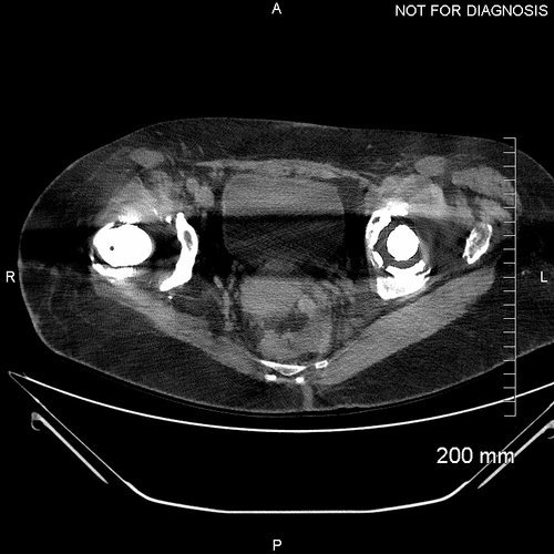
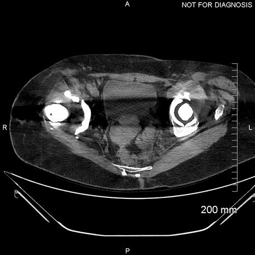


This pre-op CT scan was used to create a 3D model of the patient’s hemipelvis in order to design the custom implant. Note the positioning of the implanted femoral heads as you scroll through the images.
The Diagnosis
A Paprosky 3B acetabular defect with considerable superior migration of the existing acetabular cup. The acetabulum is flattened and the medial acetabular wall is almost entirely missing.
The Plan

Figure; (A) Anterior–posterior and (B) lateral views of the difference in centre of rotation between the Statistical Shape Model and the diseased hip - a significant difference in Y is observed.
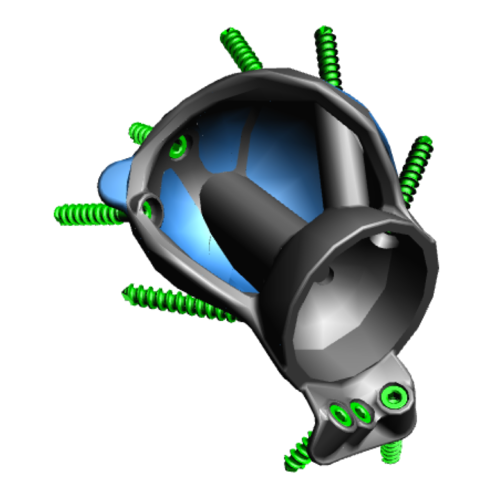
This series of images shows the design of the acetabular implant. The blue areas of the design highlight the trabecular titanium. These images are produced as part of the planning and designing stage of the procedure.

This image shows the Trabecular Titanium used with these implants. In order to manufacture this structure, rapid prototyping - better known as 3D printing - is utilised. This is made using electron beam sintering, which means the structure is continuous. The pores within the material have been shown to encourage bony ingrowth.
The Operation
We used a posterior approach to gain adequate exposure of the acetabulum and the femur. We progressed to release psoas and gluteus maximus from the femur, and the abductors from the ilium.
The acetabular bone was prepared with reamers according to the 3D computer plan. We used 3D-printed sterilised plastic models of the acetabulum to guide us. Two models were used, one demonstrating the pre-operative anatomy, and one demonstrating the preparation we were aiming to achieve.
A trial 3D printed model of the acetabular cup was introduced to assess the bony preparation. When we had achieved the plan, we introduced the 3D printed trabecular titanium implant. This was secured with 3 screws. Dual mobility bearings were used in the cup.
Finally we used a cement-in-cement small sized stem on the femoral side, which allowed us to adjust for femoral offset and the leg length. We then washed the operative site and closed after a series of thorough checks assessing the stability of the joint and the length of the leg.
The Outcome

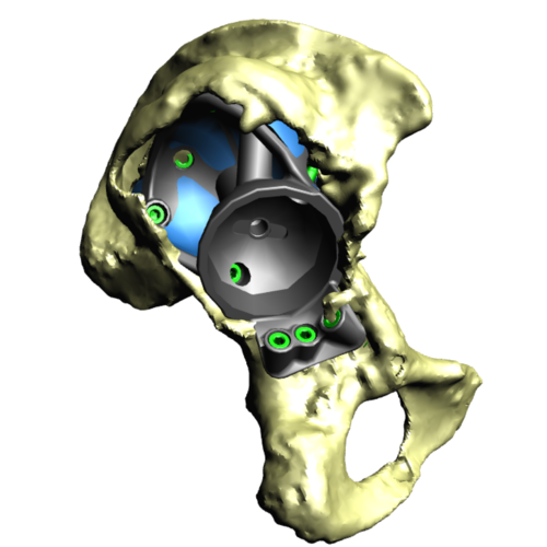
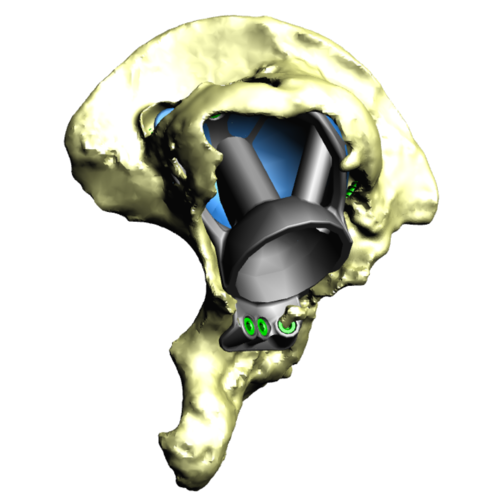
Three-dimensional models of the case showing the planned position of the component (green) and the post-operative location of the component (blue).
Accurate pre-op planning and the adoption of custom 3D printed implants are viable options in the reconstruction of massive Paprosky-type acetabular defects showing promising short-and medium-term results in complex hip revision surgery.
Although challenging, LLD and gait abnormalities can be greatly improved with the aid of accurate surgical planning. Surgeons and engineers should consider the integration of EOS imaging in surgical planning of reconstruction of large acetabular defects.

Anteroposterior plain radiograph taken post-operatively. The large custom implant is in situ filling the defect made by the superior migration of the old implant.

The leg length discrepancy has been corrected using the 3D printed trabecular titanium implant

EOS image - a post operative sitting EOS image with the implant in situ.

A comparison using EOS of the pre-operative and post-operative leg length discrepancy
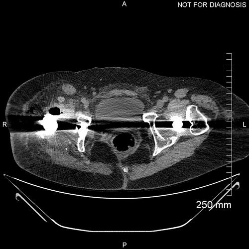
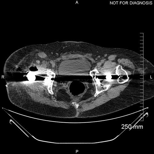
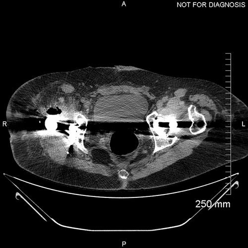
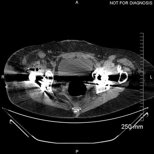
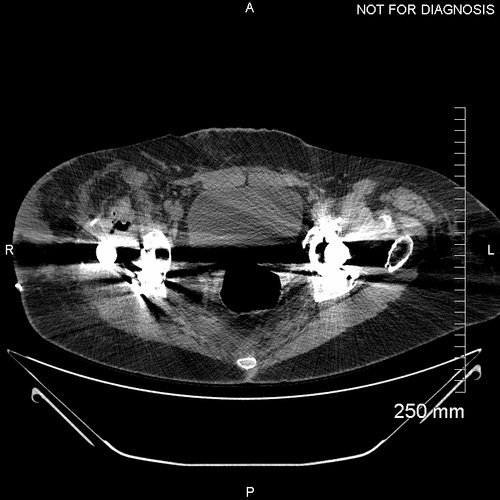
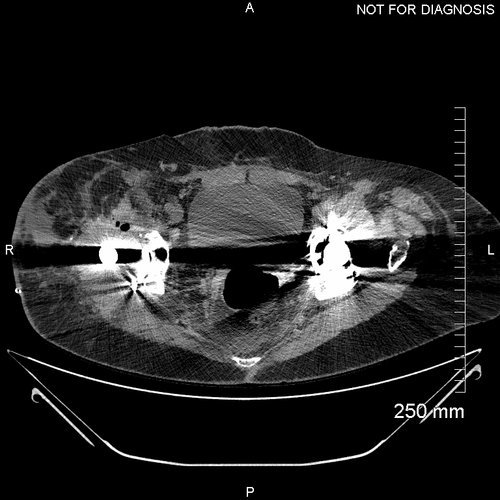
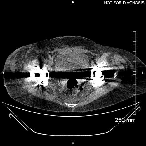
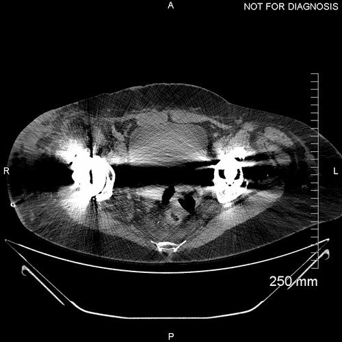
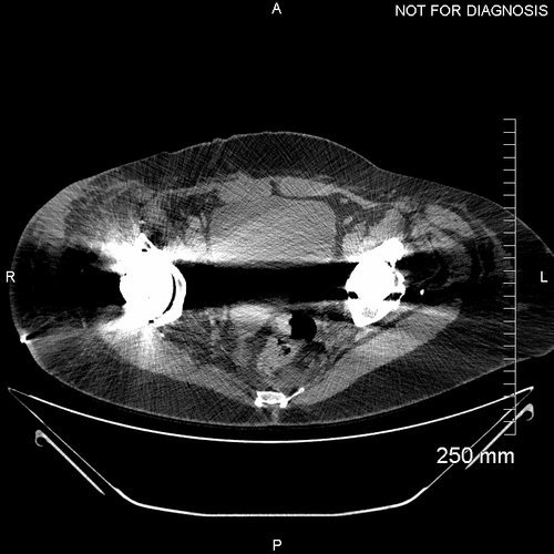
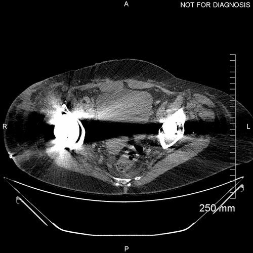
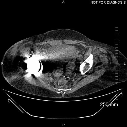
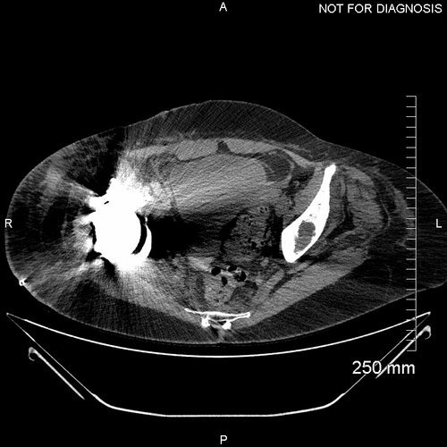
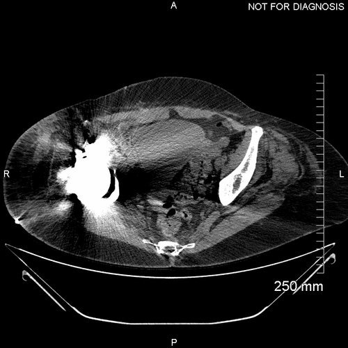

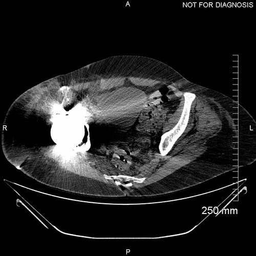
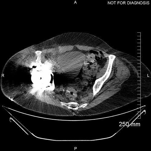
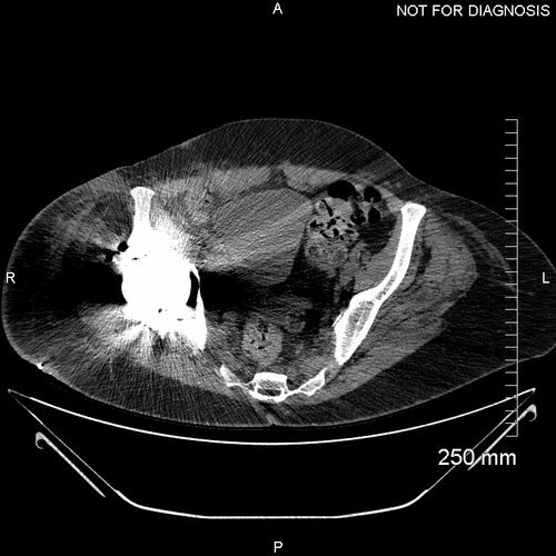
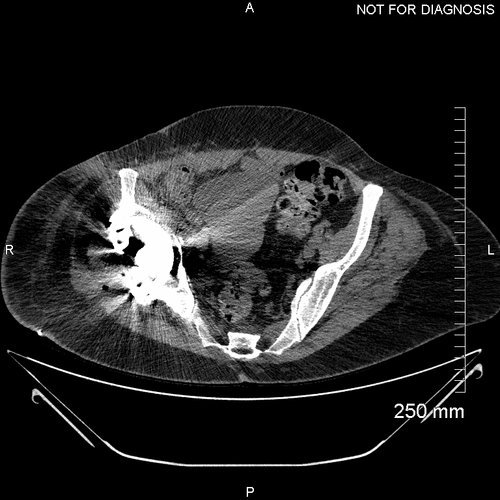
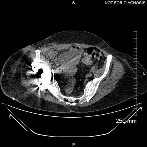

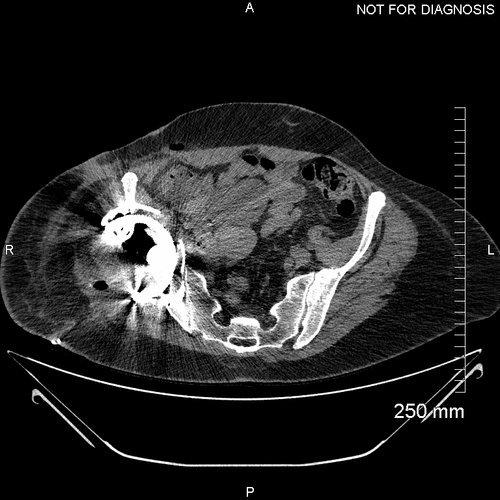
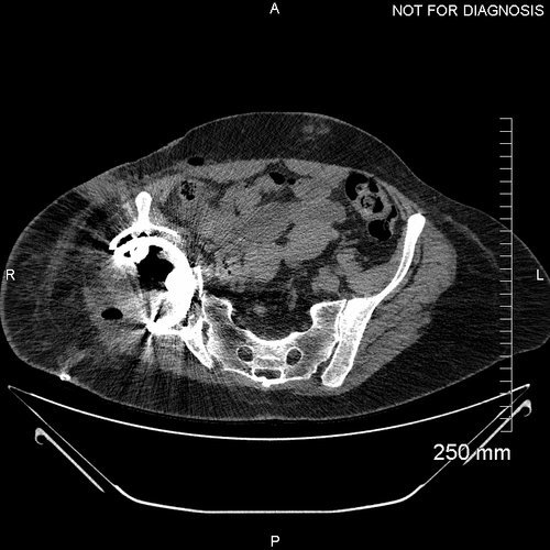
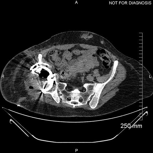
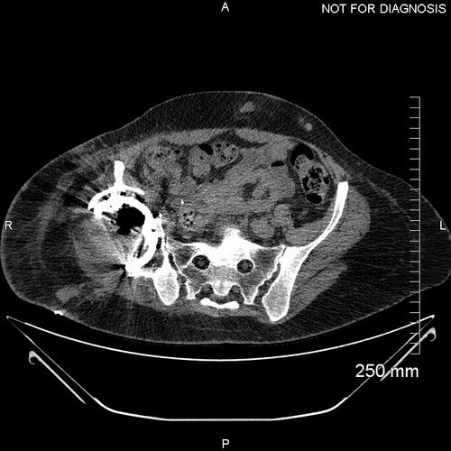

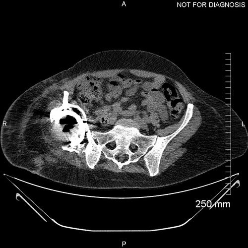
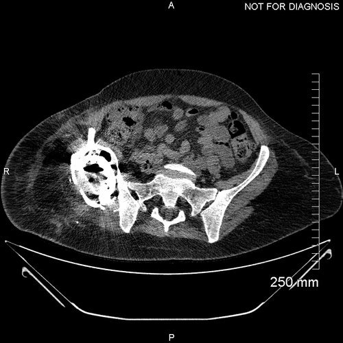
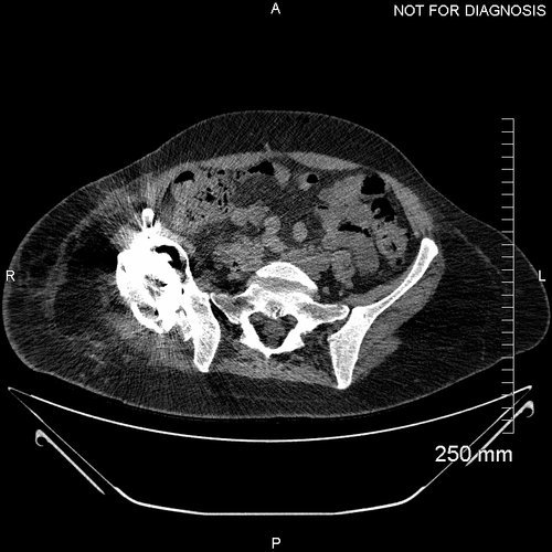
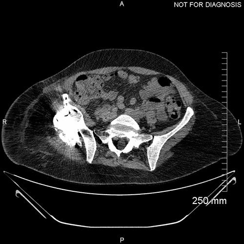
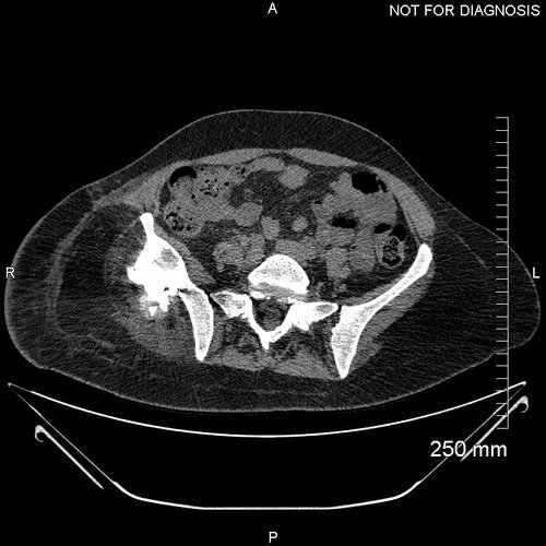
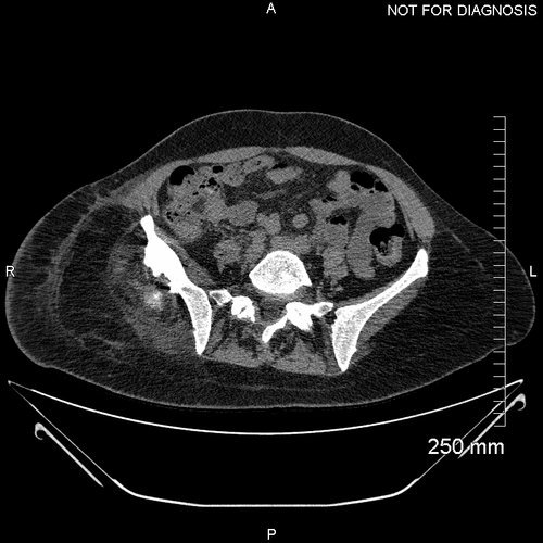
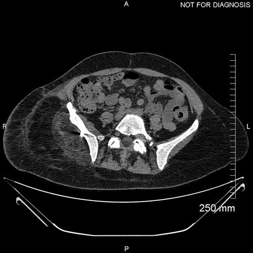
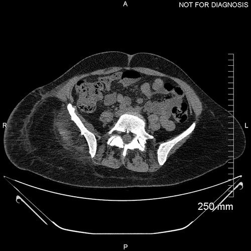
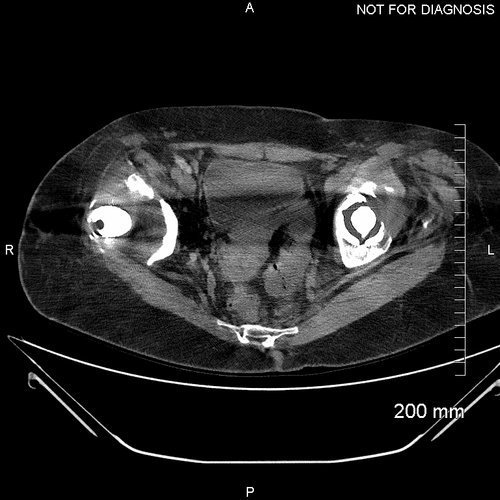
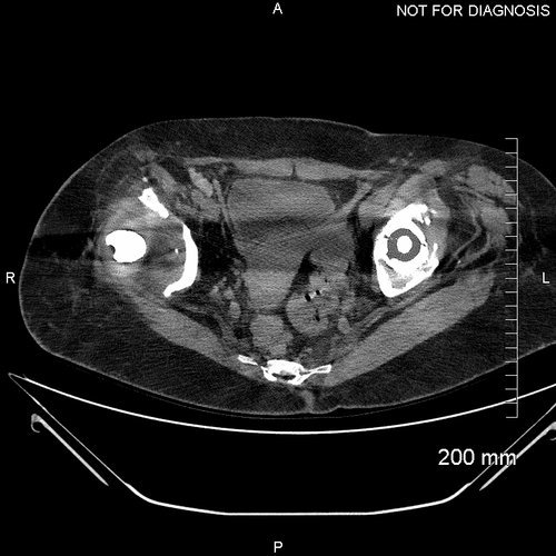
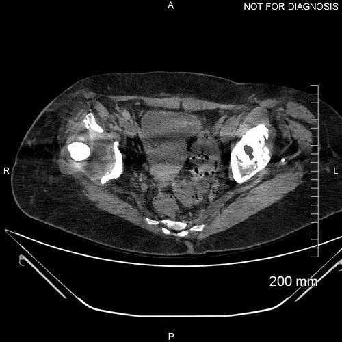
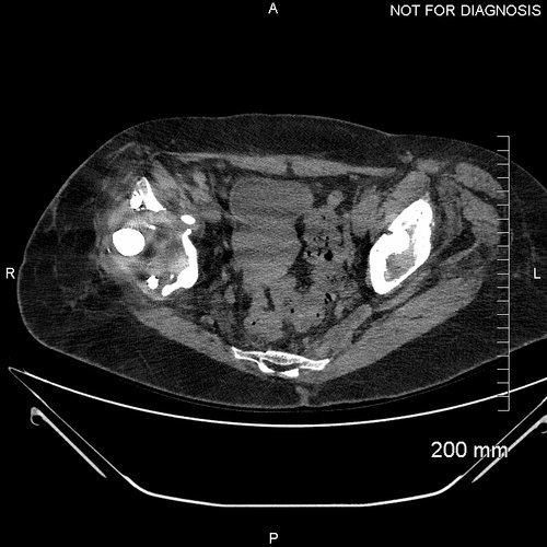
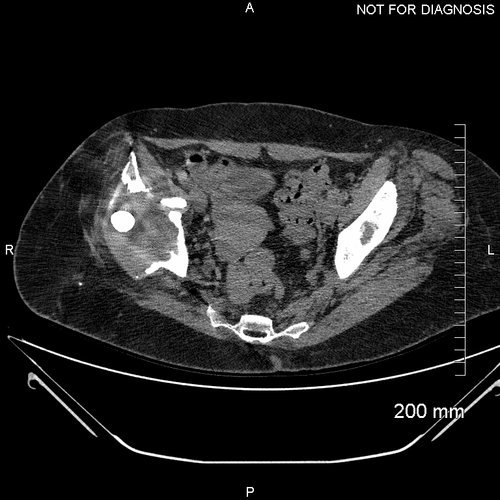
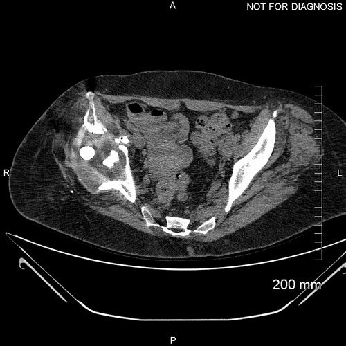
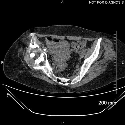
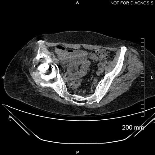
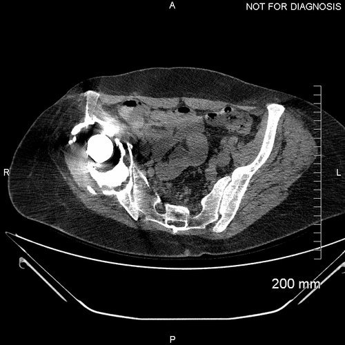
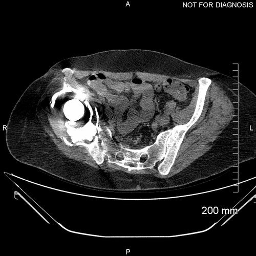
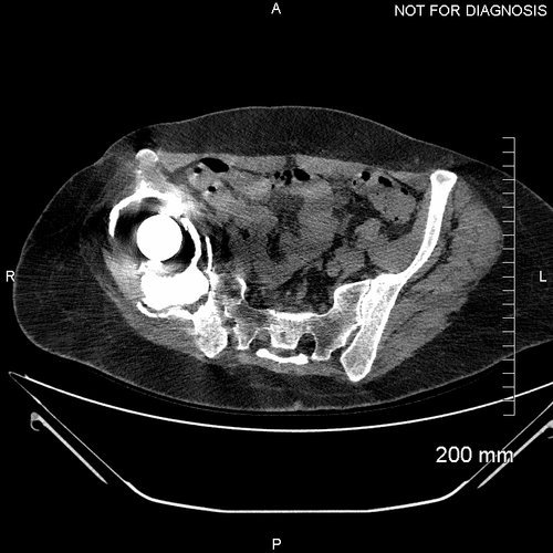
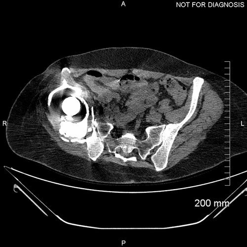
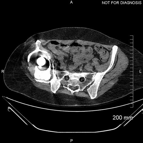
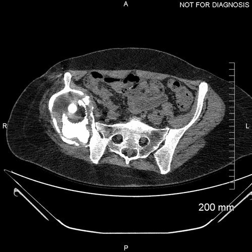
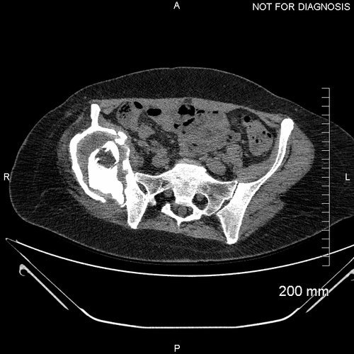
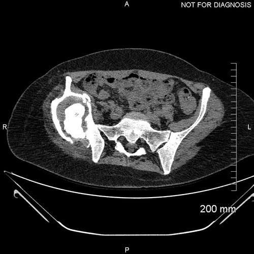
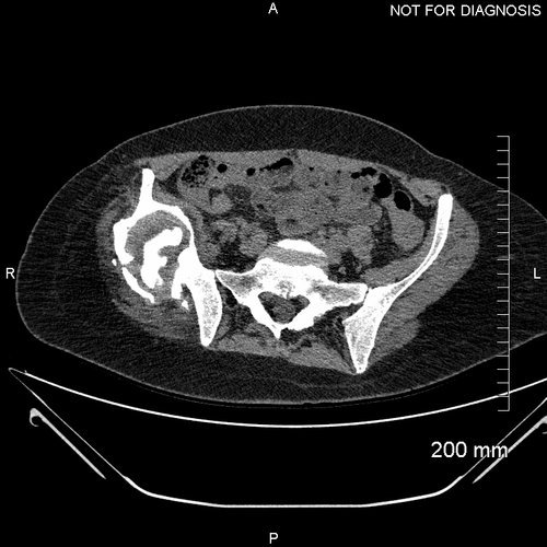
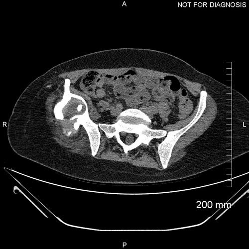
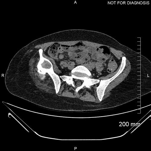
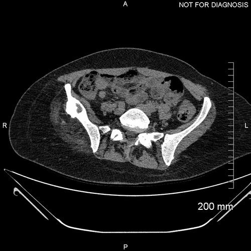
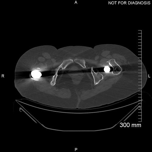
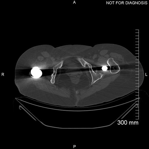
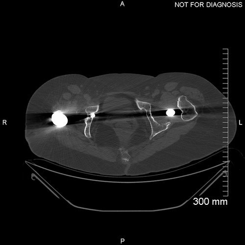
Post-Op CT taken 10 days post-operatively to assess the position of the component.

One Year Post-Op Radiograph AP - This radiograph at one year demonstrates no implant migration. The function of the new hip joint was very good, with the patient able to walk without a leg length discrepancy.
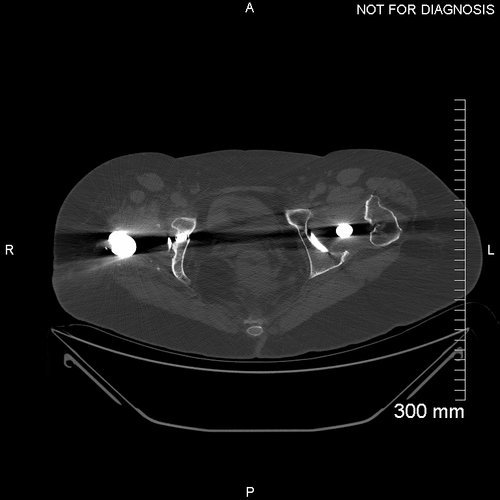
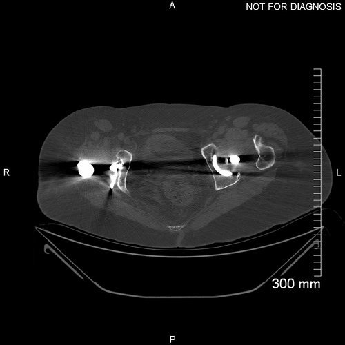
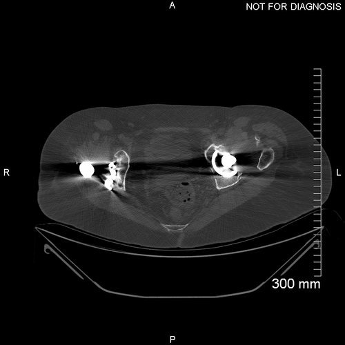
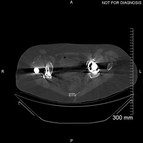

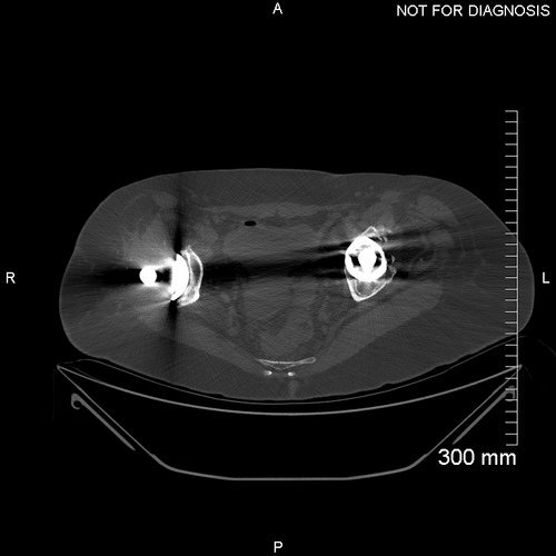
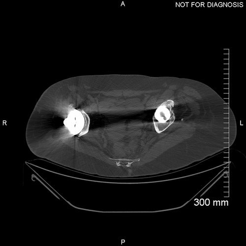
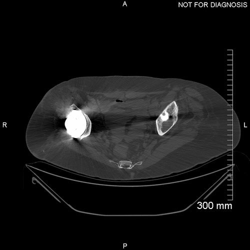
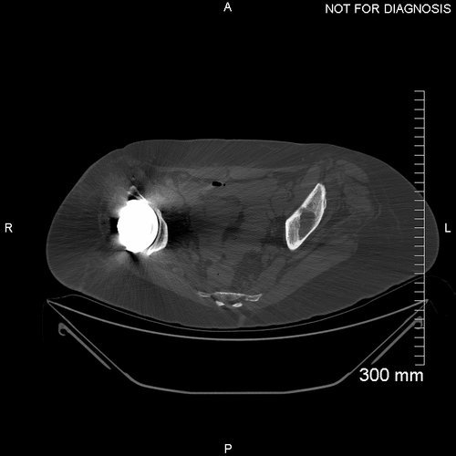

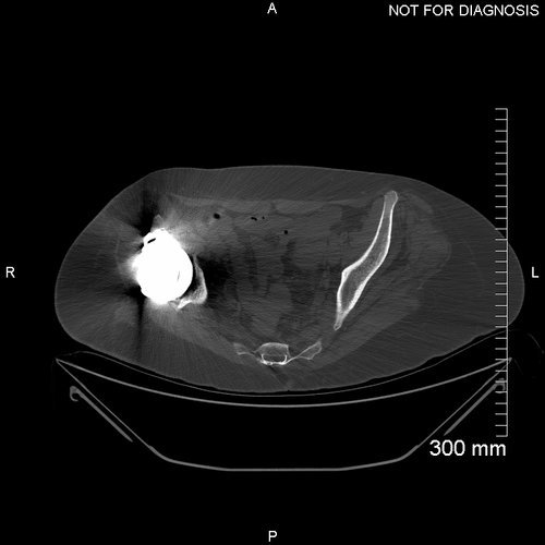
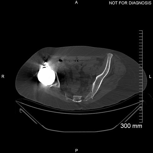
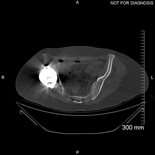
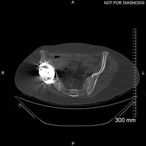
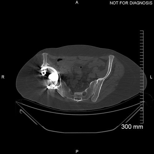
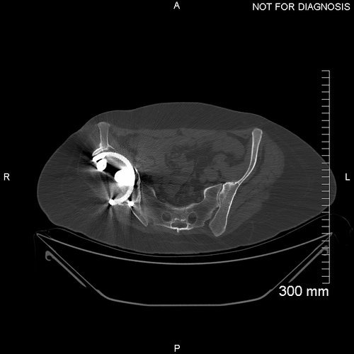
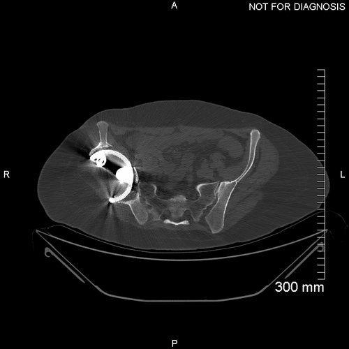
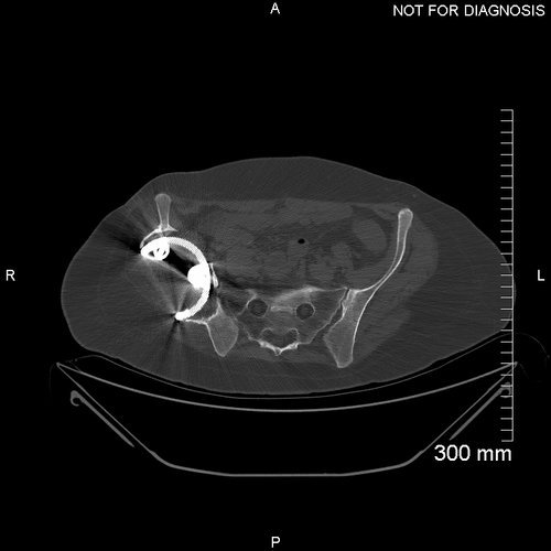
One year Post-Op CT - a repeat CT scan taken one year later at follow-up demonstrated there was no component migration.

One Year Post-Op Radiograph Lateral also demonstrates no implant migration.
Five year post-operative AP radiograph – This radiograph shows no implant migration, there is direct contact between the implant and the adjacent bone confirming good fixation and stability.
The Verdict
“At 8-weeks post-op, the pain in the Rose’s right hip had been resolved and the joint had a full range of movement. There was some evidence of foot and ankle weakness
At one year post-op, clinically the leg lengths are almost equal, a huge improvement on the pre-operative discrepancy. The antalgic gait that was present pre-op is no longer present.
6-Year post-operatively radiographic evaluation of the implant showed bone ingrowth at the bone-implant interface and no evidence of implant loosening or migration.”
-
The use of pre-operative and post-operative EOS scanning allows for accurate measurement of the change in leg length discrepancy
Custom implants can be used to achieve an initial strong primary fixation in huge acetabular defects. This patient at 8-weeks post-op was pain free with a good range of movement
-
-