CASE 43: Using 3D printed guides to achieve the best possible position of hip replacements

The Story
“This 76-year-old lady presented with pain in her right hip, which had been progressively deteriorating over the last year. It was starting to prevent her from driving.
She had a previous nephrectomy for a benign tumour, but otherwise she was fit and healthy.
Examination revealed a good range of lumbar spine movements but a reduced range of right hip movements which were irritable. She had pain in her right groin throughout the examination.”
The Evidence

This is an anteroposterior radiograph showing end stage osteoarthritis of the right hip causing this patient pain and discomfort.
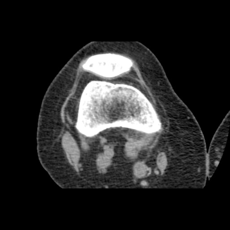
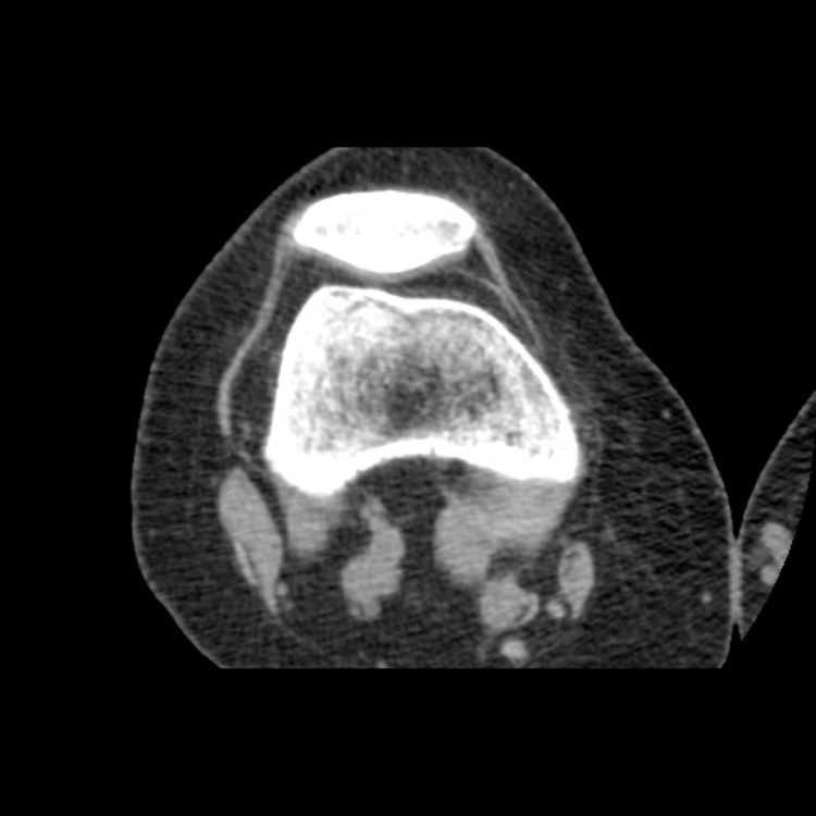
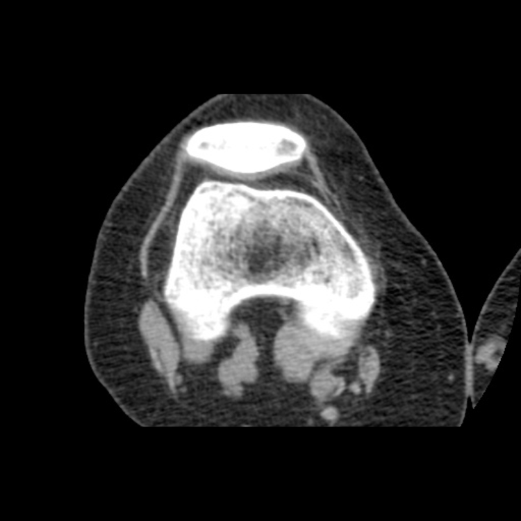
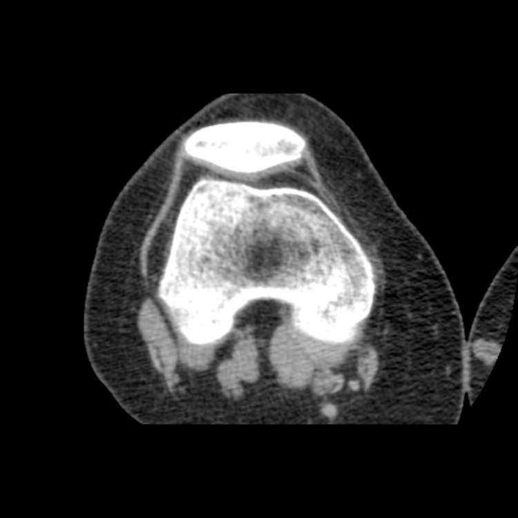

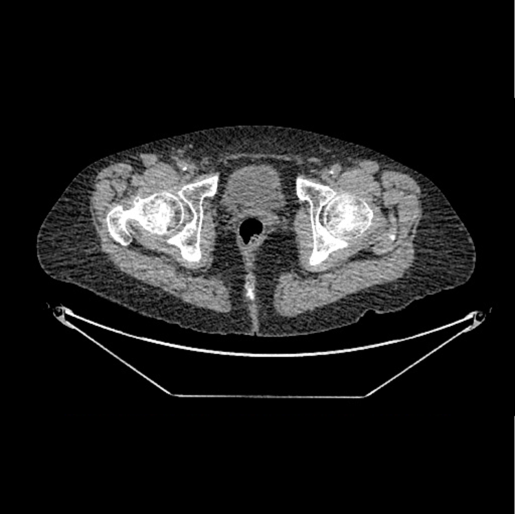
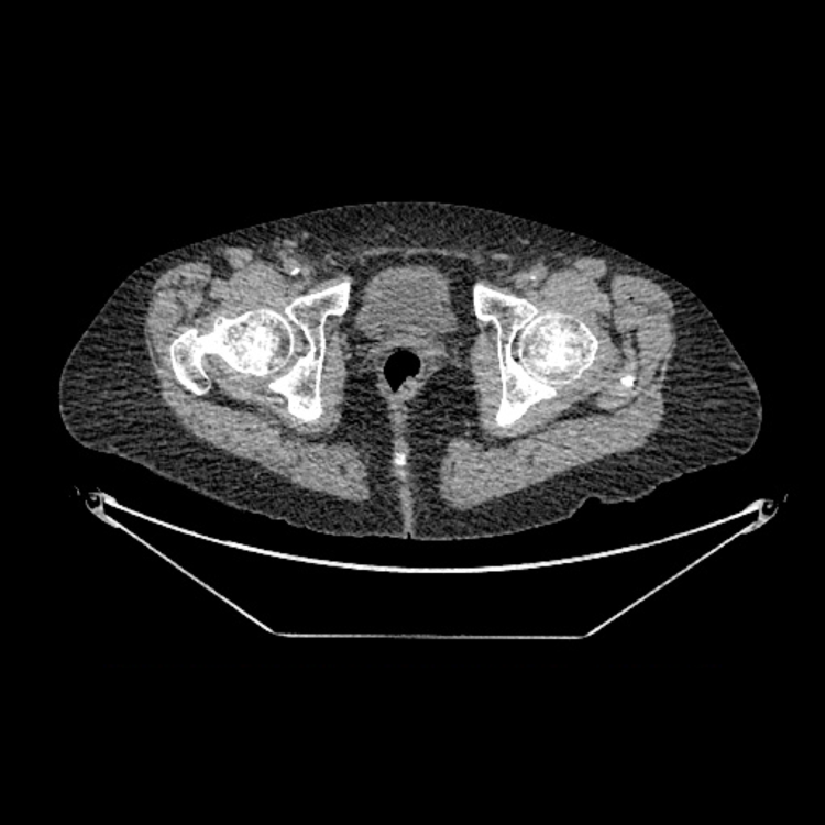
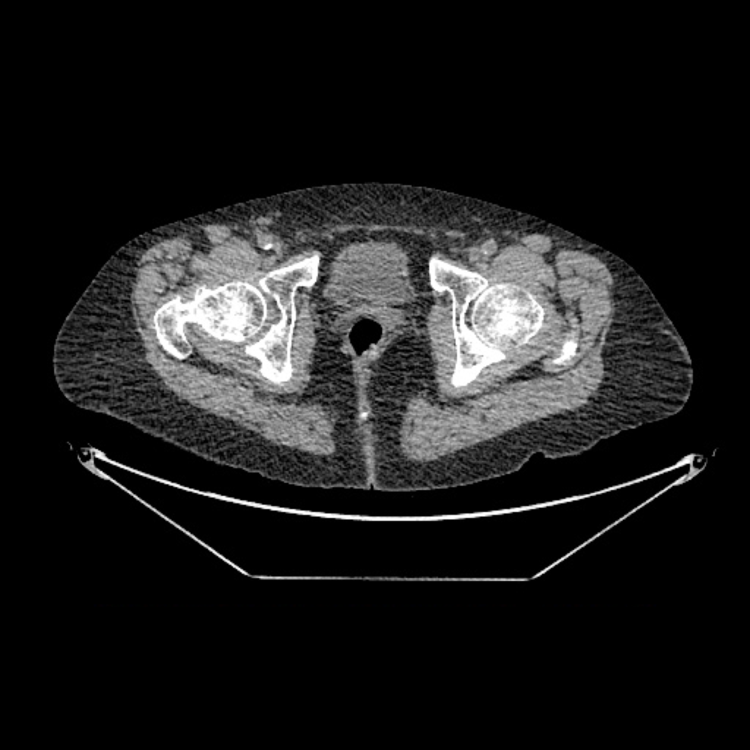

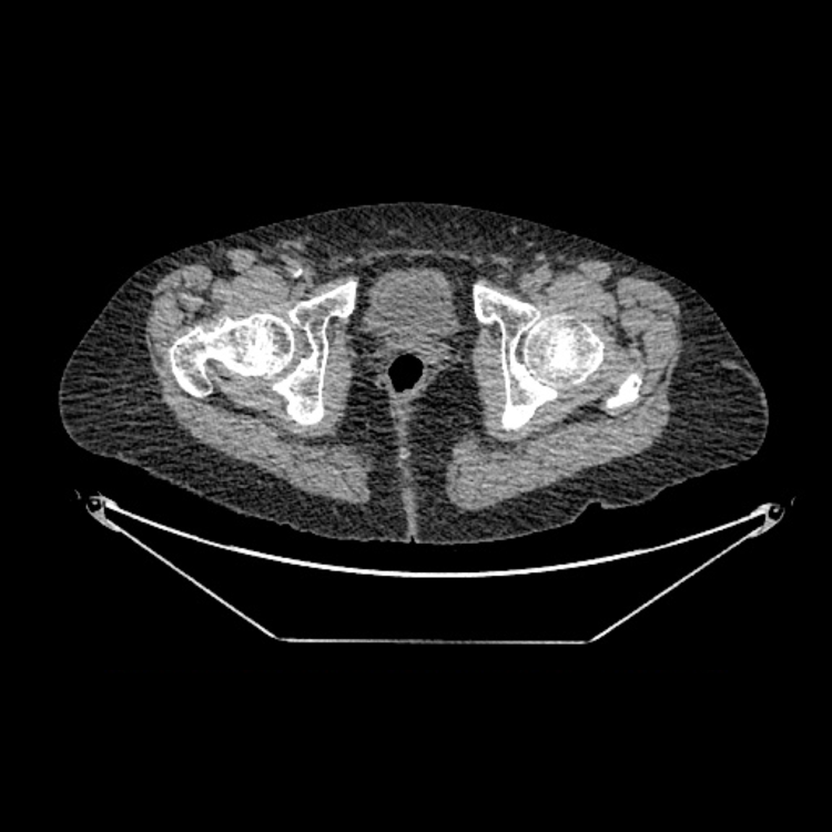
Thin slice CT scans are used to produce a 3D model of the patient's bony anatomy to allow for the PSI jigs to be produced. Slices through the knee are also required to allow for planning.
The Diagnosis
A painful right hip secondary to end stage osteoarthritis requiring a total hip replacement using patient specific instrumentation.
The Plan
To optimise the implant position, the patient underwent a CT scan to plan her procedure. From the CT scan, a 3D virtual model of her pelvis and right proximal femur was produced. This was used to plan the procedure virtually.
From these models and the plan, patient specific instruments (PSIs) were designed and produced to guide the surgeon to aid in obtaining the optimal position of both the femoral and acetabular component.
The jigs are explained below.

Femoral Model and Jig
This is an image of a PSI femoral jig sat on a 3D printed model of the patient’s proximal femur.
This jig is designed for the posterior surgical approach, and is also complementary to the patient’s anatomy.
It is used to aid in the cutting of the femoral neck, to ensure the position and the angle of the neck cut is correct.

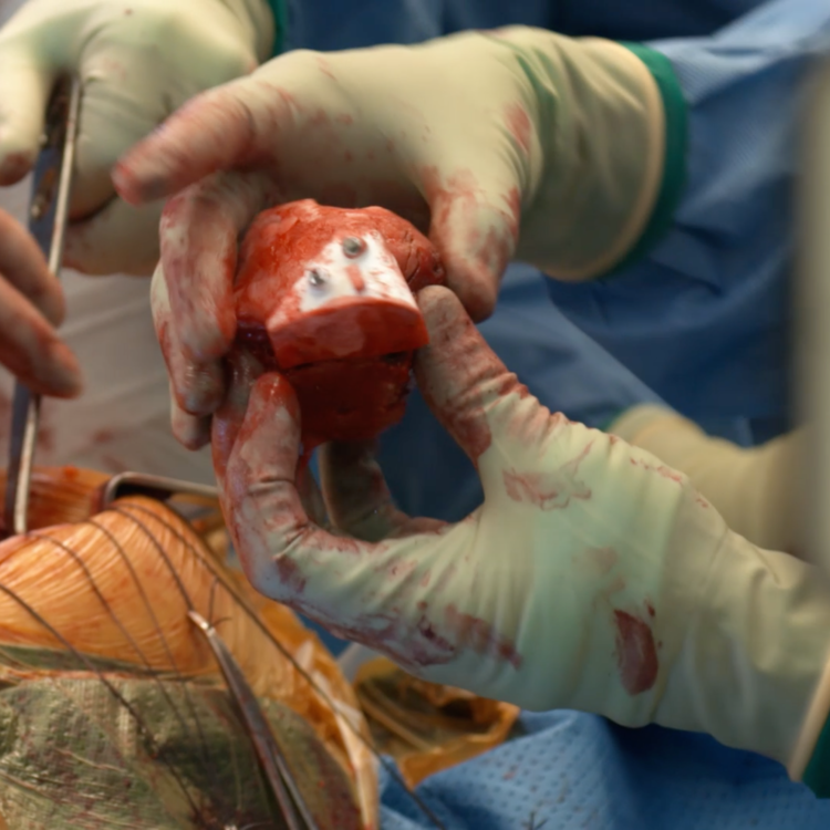
Acetabular Model and Jig
This is a photo of a PSI acetabular jig sat in a 3D printed model of the patient’s acetabulum.
The jig is custom made to fit into the patient’s own acetabulum. The left arrow shows the points where the jig is complimentary to the patient’s anatomy to get an exact fit.
The right arrow shows the drilling guide. When the jig is sat correctly in the patient’s acetabulum, the drilling guide is used to place two pins onto the pelvic bone. A visual guide (pictured below) is then slid over these pins and aids the surgeon in getting the reaming angle correct.
The Operation
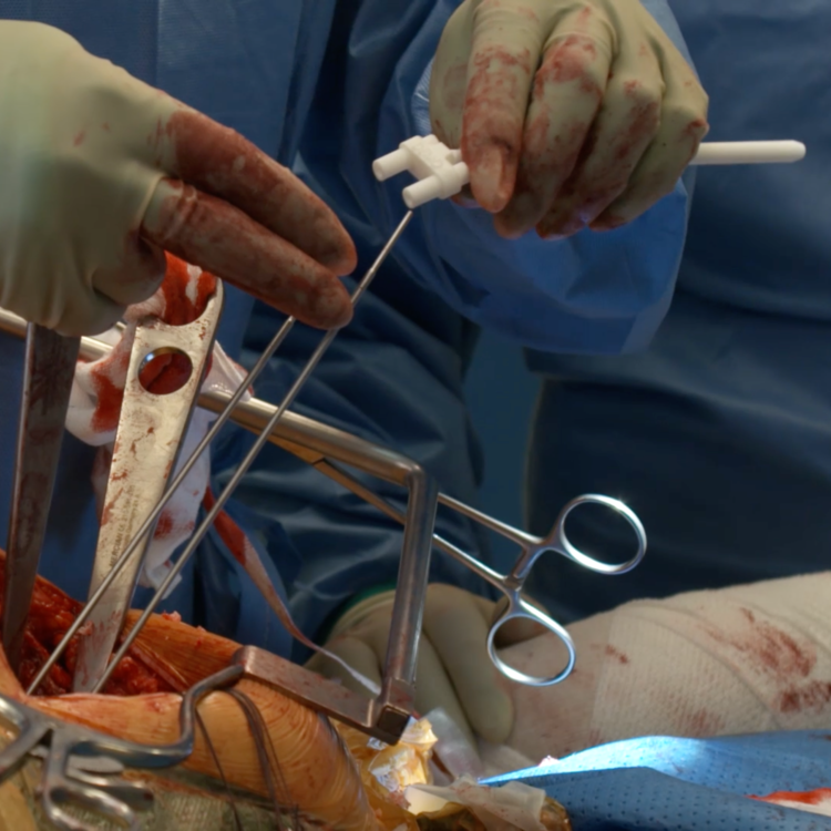
This series of three photos shows the intraoperative use of the femoral jig.
Image one shows the placement of the femoral jig on the posterior of the proximal femur.
Image two shows the jig, pinned in place, being used as a cutting guide to remove the femoral head.
Image three shows the femoral head being removed with the jig attached.
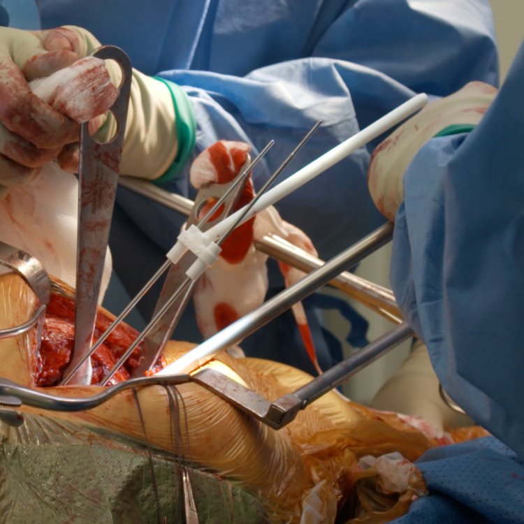
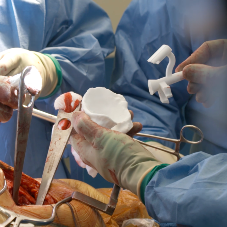
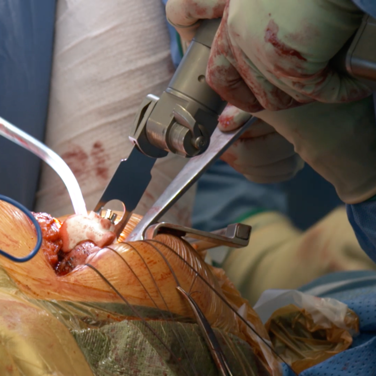
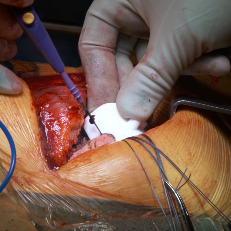
This series of three photos shows the intraoperative use of the acetabular jig.
Image one demonstrates the acetabular model and jig being used to visualise the positioning of the jig within the acetabulum. Pins are then drilled into the acetabular bone using this jig.
Image two shows the visual guidance bar being slid over the two precisely positioned pins.
Image three shows the surgeon lining the trajectory of the cup with the visual guidance bar to ensure optimal positioning.
Key surgical steps
CT planned PSI total hip replacement using a posterior approach
The femoral jig is used to guide the femoral cut, to remove the femoral head
The acetabular jig is used to guide the surgeon in reaming for the planned socket, to maintain the correct trajectory to obtain an optimal position
The Outcome
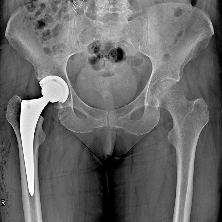
Post-operative radiograph shows the primary right sided total hip replacement in a good position after implantation using PSI.
The Verdict
The patient was extremely pleased with the outcome of the surgery, as it has vastly reduced the pain in her right hip. The left hip will be revised in the near future.
3D CT planning is essential in complex cases. The use of patient specific implants can aid the surgeon to obtain the optimal implant position. This adds a few minutes to the operation, but if the optimal position is achieved it will possibly add years to the life span of the implant.