CASE 11: Revision of a loose cup due to massive circumferential acetabular osteolysis from polyethylene wear, using a custom 3D-printed cup

The Story
“The patient is a 62-year-old male with bilateral total hip replacements. These were thought to have been completed approximately 30-years ago.
He presented with pain in both legs, worse on the right and localised to the knee. A CRP of 5 ruled out infection.”
The Evidence

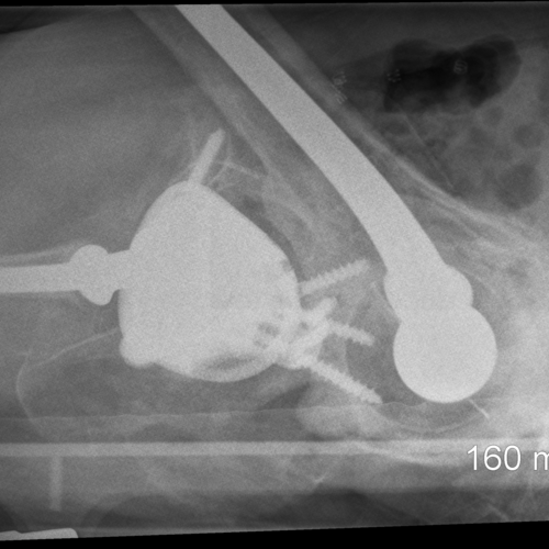
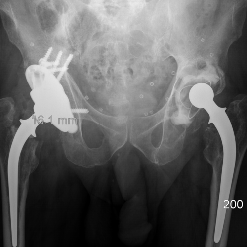
Pre-Op Radiograph shows loosening of both acetabular components. From the radiograph it is difficult to gauge the size of the acetabular defect
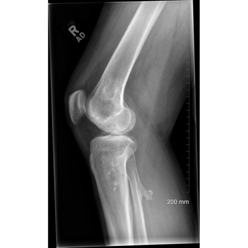
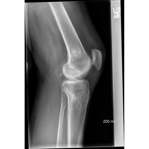
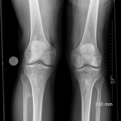
Pre-operative radiographs of the knees were to identify if degenerative joint disease in the knees was causing the reported knee pain. Some degenerative disease is present, however the source of the pain is the loosened acetabular component in the right hip
The Diagnosis
Loose right acetabulum of a metal-on-plastic THR with some subluxation. Loose left acetabulum.
The Plan
The initial plan was reconstruction of the right hip with an augment or a restoration cup. Intraoperatively, the decision was made to convert the procedure to a girdlestone.
The defect was too large for reconstruction with a cage, restoration anatomic cup, augments or bone graft.
CT was completed post-op to design a custom acetabular implant.
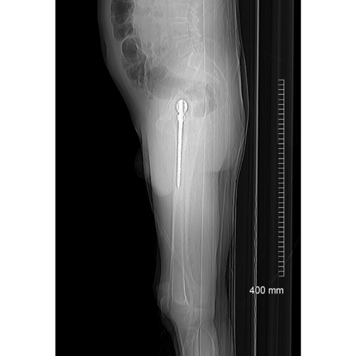
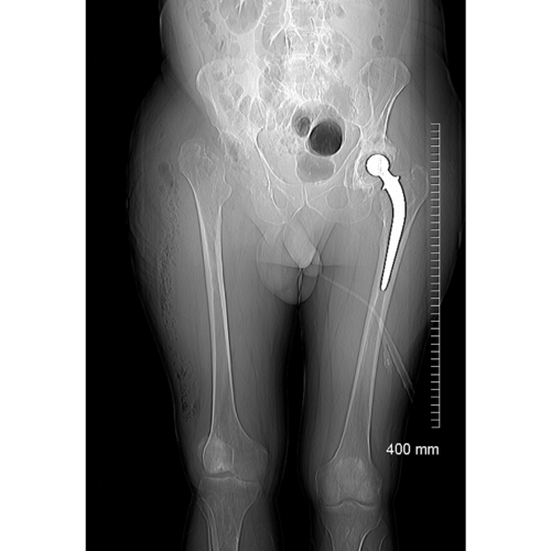
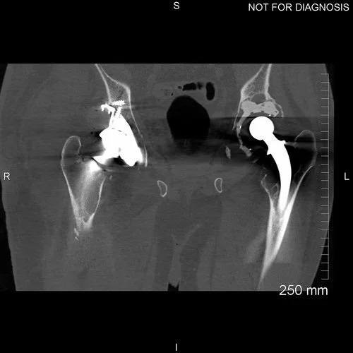
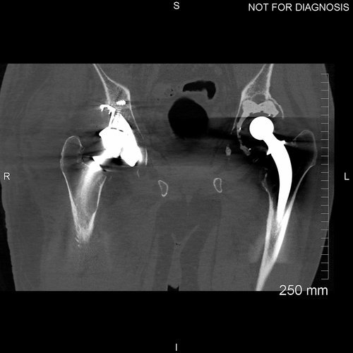
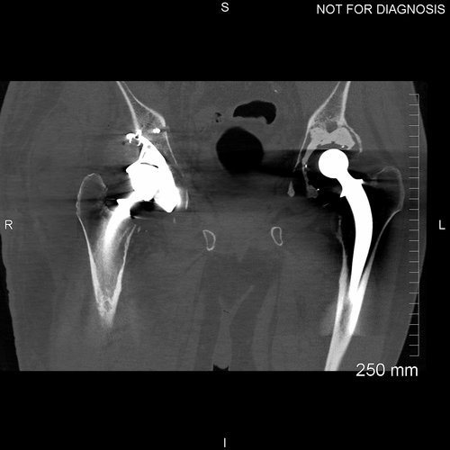
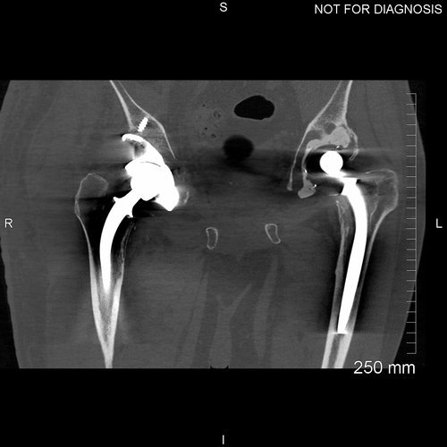
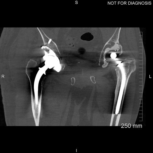
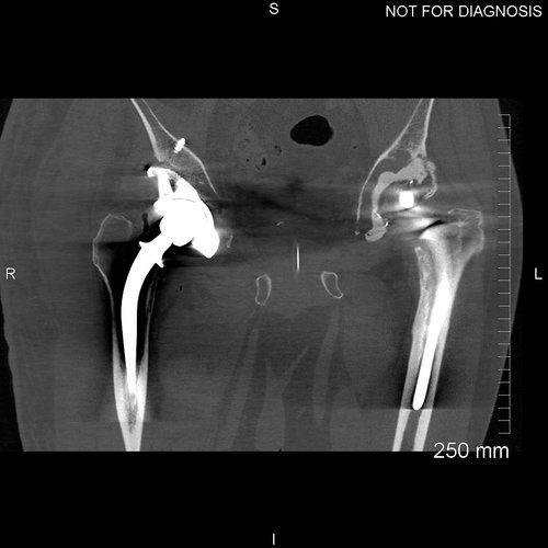
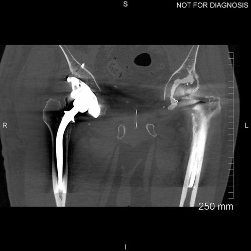
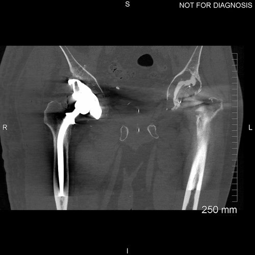
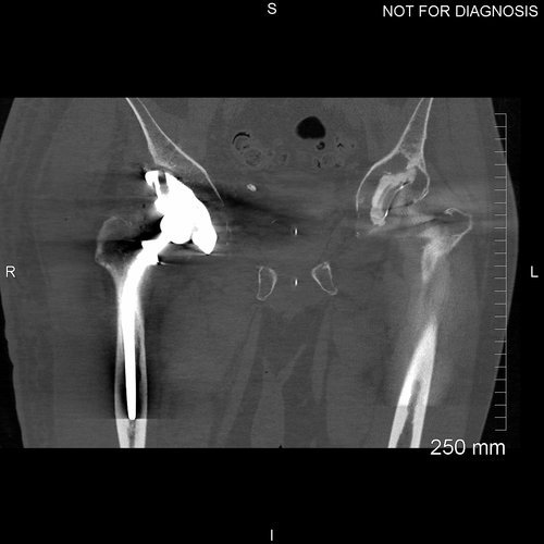
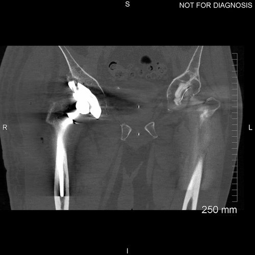
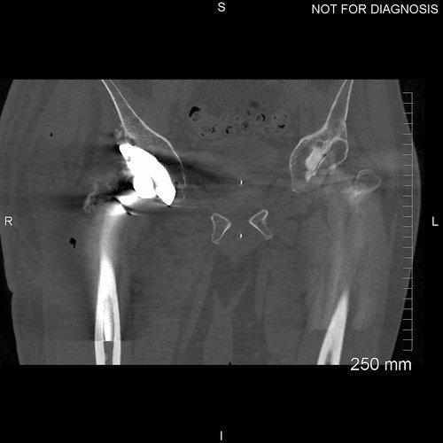
Scannograms show the pre-operative situation before the second stage of this patients procedure


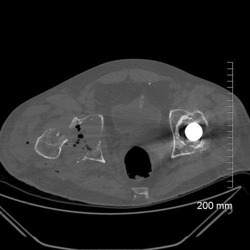

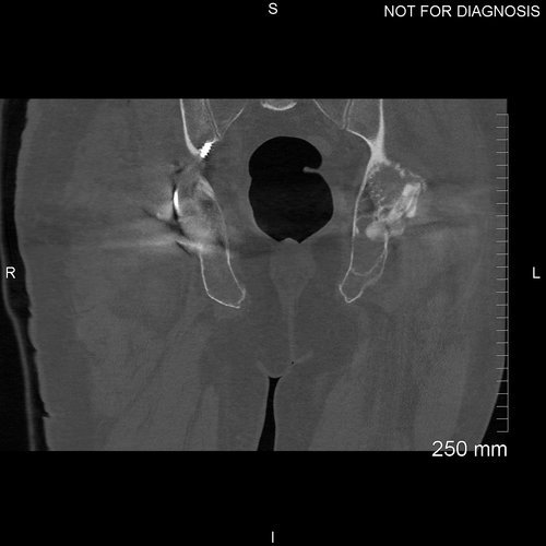
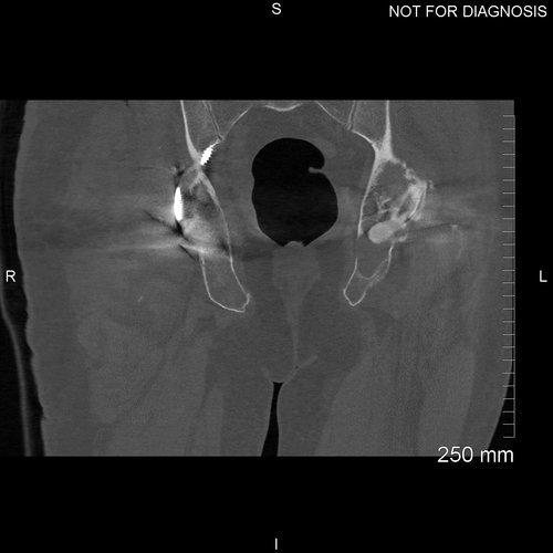
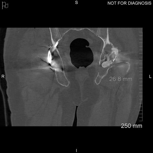
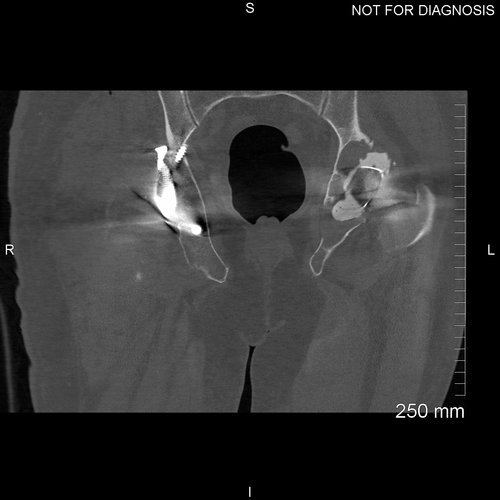
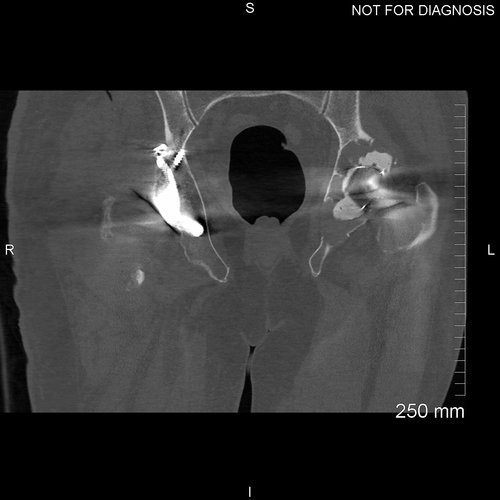
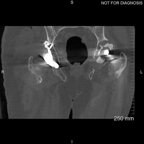
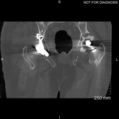
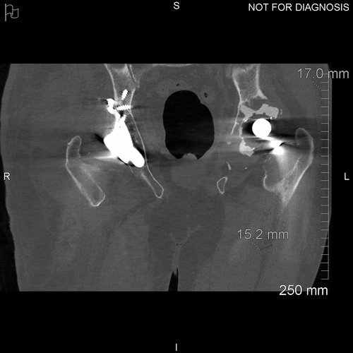
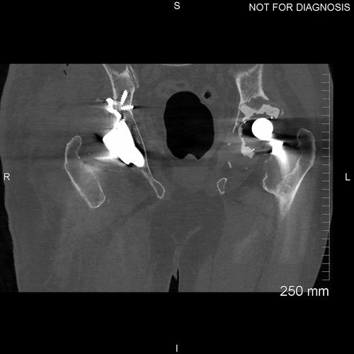
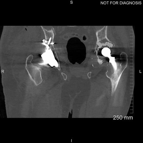
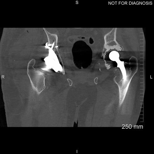
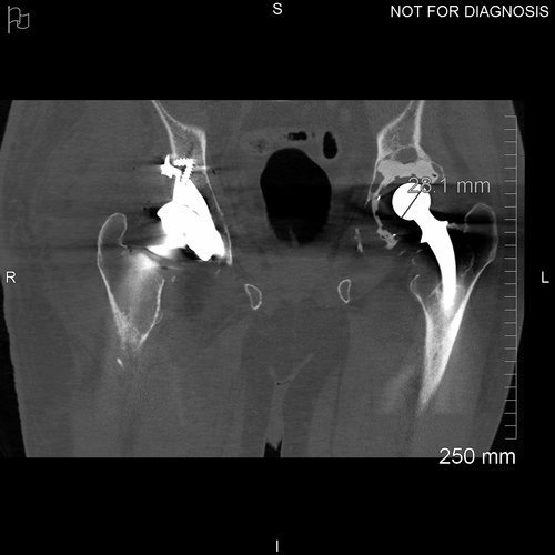
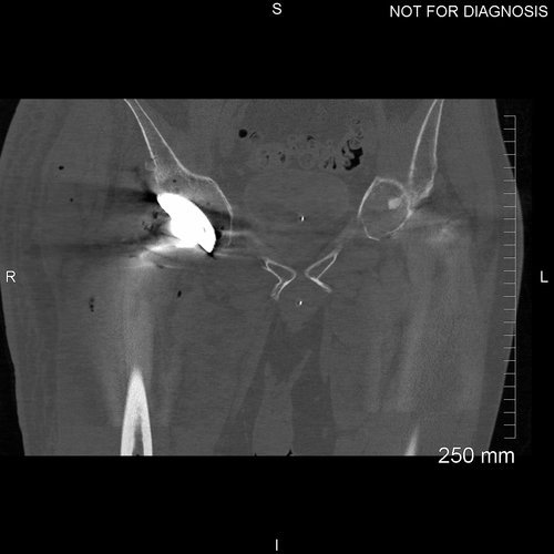
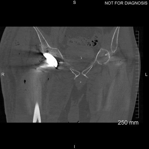
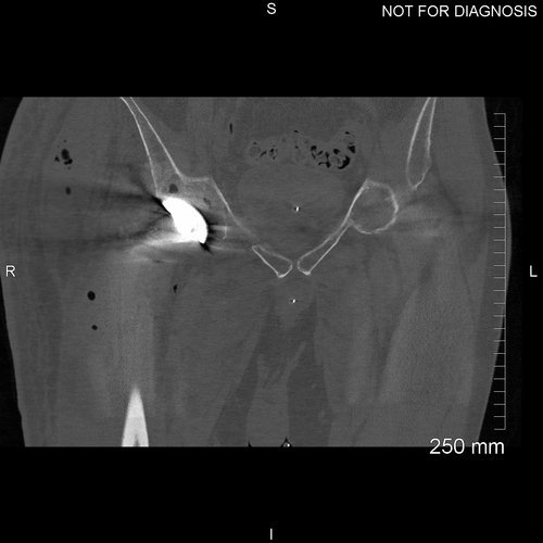
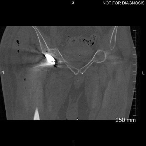
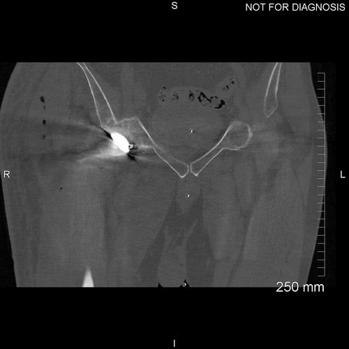
Axial CT - used to design the patients custom implant. Above is just a few slices. Note how thin each CT slice is; 1mm slices are used in the design protocol
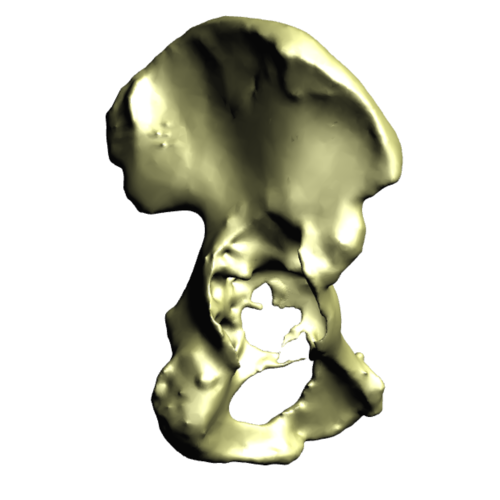
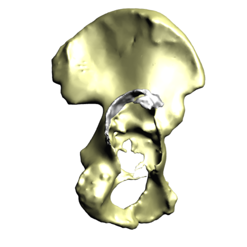
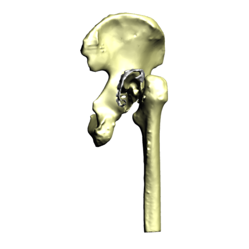
Hemipelvic defect - This is a 3D model of the patients hemipelvis, reconstructed from the CT scan taken after the first stage procedure. This demonstrates the size of the defect which is very difficult to appreciate from the initial radiograph. The second image shows existing bone cement.
Treatment Stage 2
The second stage of the procedure included implantation of the custom acetabular component.
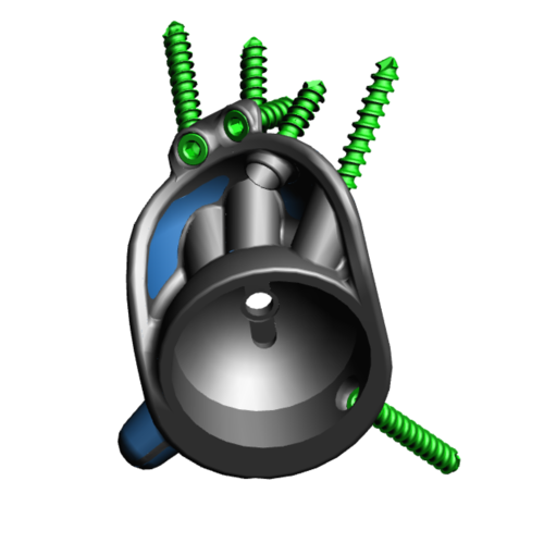

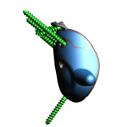
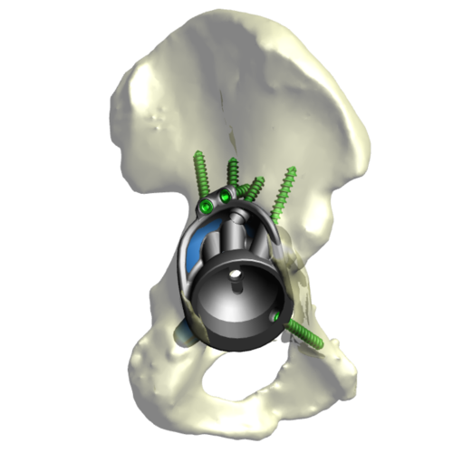
This series of images shows the 3D design of the implant created specifically for this patient. The areas in blue will be manufactured out of trabecular titanium to encourage bony ingrowth and osseointegration of this implant

This image shows the structure of the 3D printed trabecular titanium metal used to produce these implants. This is designed to contact the bone to allow for bony ingrowth to occur
The Operation
Key surgical steps:
Old incision was used to gain access - Posterior approach
Socket was prepared as per the custom plan
Custom implant was inserted with very good screw fixation
Dual mobility bearing was used
Cement in cement femoral stem
Good length and stable
Wash
The Outcome
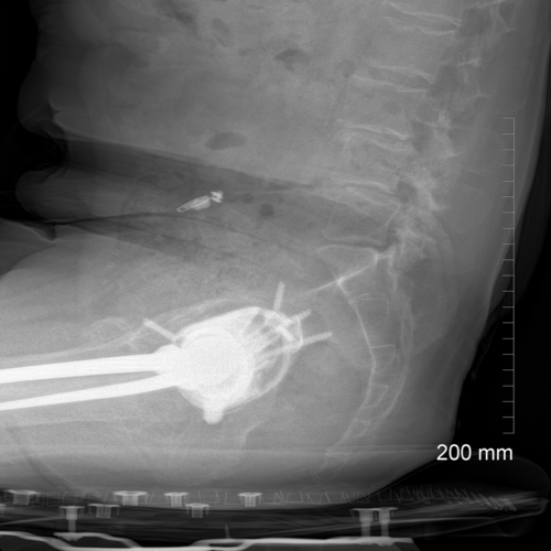
Post-operative radiograph shows the custom implant in situ. Note the existing stem was retained
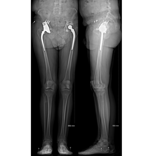
Post-operative EOS images demonstrate the functional position of the acetabular implant. Note the level of the knees and the flat pelvis, demonstrating that there is no leg length discrepancy post-op


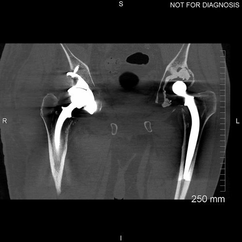


Post-operative CT scan to assess the position of the implant within the bony pelvis
The Verdict
“The patient returned to clinic 7-weeks after his operation.
He was mobilising well using two crutches as advised with the plan to reduce down to a single crutch on the left side
The patient is happy with the outcome of his revision.”